Sunday, August 28, 2016

Making Clapham Yard Usable Again


This week I was really crook and spent a couple of days at home and did not get anywhere near the shed.  However, Saturday at about midday was another story.  I ventured down and started work on the southern end of Clapham Yard.  Firstly I soldered power jumpers to each of the tracks at the south end of the yard.  I also wired up the two relocated points motors.  I then reviewed the programming on the NCE Mini-panel that controlled the southern end of the yard and identified where I had to change the programming as I removed some points from various routes.  Basically 5 of the 7 routes are now working from the old control panel.  I drilled two more holes in the control panel and moved one push button and added another one.  However, these two new routes will have to be controlled from another mini panel – the northern end one, as there are no longer any free buttons in the existing southern mini-panel. 
My very expensive control panels.  I have not rubbed out the old lines, nor filled the hole left by the moved push button.

While testing the power connections out on the southern end of the yard, it became obvious that I had made my dual gauge track very tight.  So I slightly widening it bit by bit with the help of my soldering iron.  Levering the third rail out slightly.  After this was done, I had no issues running my 1550 up and down all the tracks.

So after completing this work, I decided to re-attach the layout lighting to the section above the northern end of Clapham Yard.  I first added a small extension onto the southern end of the lighting pelmet above The Risk.  I then added two new ‘L’ brackets to attach the pelmet supports to the wall.  I then cut a new pelmet to joining the section from Clapham Yard to The Risk section. 

After lunch on Sunday (after doing some garden work for the boss) I added the metal reflector to the pelmet and then reglued in the LED strip. I then ran the power cord back to the power supply and then gave the lights a test run.  Perfect!
It looks now like we have a continuous lighten from the southern end of Clapham Yard all the way around to The Risk.

I then decided to wire up the two changed push button on the southern Clapham Yard Panel back to the mini-panel at the northern end.  I just had enough wire.  They have been tested and work well.  I have also hand drawn where the new push buttons will go on the northern panel.  I also identified what point was what number and tonight I will write out the changes for the mini-panel so I code it up this week. 
The mini-panel in question with the new connection in locations 17 and 18 on the left and northern control panel with the new button locations drawn on the panel.  Again the old connection shave not been rubbed out yet.  I will have to lay a new wire back to mini-panel for the new button.

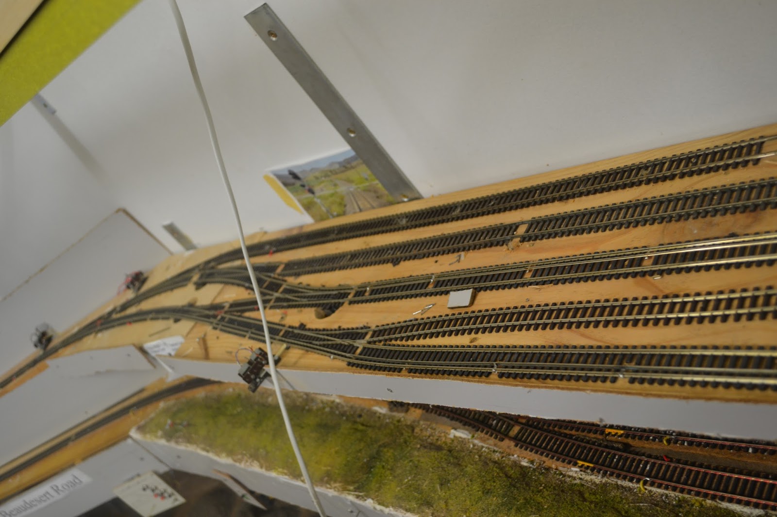
I then set about wiring up the two moved point motors at the northern end of Clapham Yard.  At this point in time, the motor on the left works like a charm, and the one of the right has a huge bind somewhere in the throw chain and nothing moves even though the motor is trying to move it.  Well that will be next weeks job.
The two new point motors located away from the points and using wire under the track to activate the points.

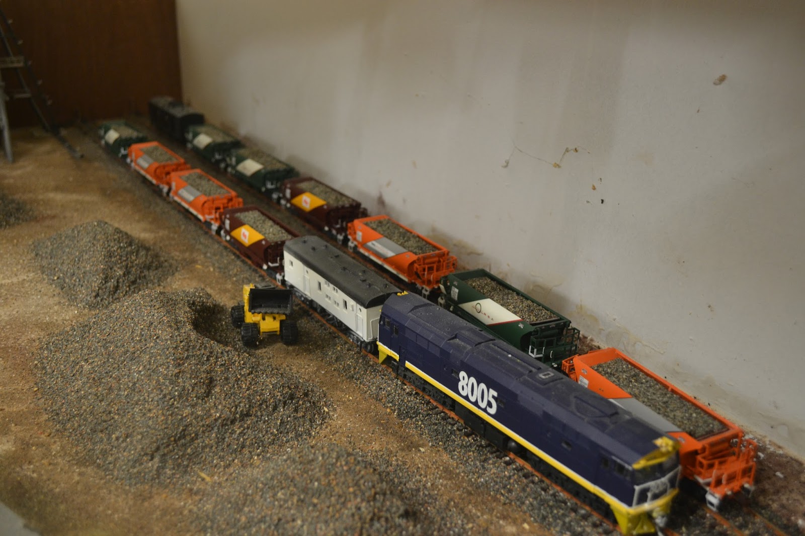
So the last shot shows the current view of Clapham Yard populated with a few locos and wagons and everything works up to this position in the yard.  More jumpers need to be added to the northern end next week.
The now half usable Clapham Yard.

Monday, August 22, 2016

Ripping up Clapham Yard


I had been thinking of doing some surgery to Clapham Yard for quite some time.  Well last Friday week I did exactly that.  The yard was originally to have four tracks.  But when I added the dual gauge some years ago, it grew to 5 tracks.  Two tracks were standard gauge, two were dual gauge and one was narrow gauge.  I originally thought that was going to provide enough options or train movements.  But as the timetable developed, I knew that I did not have enough tracks available. 

Well after being basically ripped up on last Friday, the yard grew again to 6 tracks wide.  A piece of 68 x 19 pine was added to the front of the yard.  This made the yard level of the layout the same width as the level below – Glenapp Loop.  The yard is now three standard gauge tracks, one dual gauge and 2 narrow gauge tracks.  There is also the opportunity to add a couple of sidings to the narrow gauge side. 

So here are the before photos.
The southern end of the old Clapham Yard.  The front and the third track are the dual gauge lines.  The back two tracks are standard gauge and the second from the front is narrow gauge.

The Northern end of Clapham Yard.  In the distance is Loco Pilly.  This is where various locos and railmotors bide their time between uses on the top deck.

So basically last Monday and Tuesday I completed relaying the southern entry to the Yard.  On Sunday on the weekend just gone, I managed to relay the northern end of the yard.  I have run a few wagon consists through the various points - especially the dual gauge ones that I have recently made and all seem to work almost flawlessly except for one at the northern end of the yard.  Today I started building another one to replace this one- to see if I can do a better job.  I hope to complete this tonight. 

Here are the after photos.
The new southern entry to Clapham Yard.  Three standard gauge tracks on the right, a dual gauge track and two narrow gauge tracks.  There is also a dead end narrow gauge siding visible.

The middle of the Yard shows some narrow gauge points to allow for shunting to occur on the narrow gauge railway.  On the third track is a set of scratch built ore wagons given to me from an old mate who has now left this world.  This was my test train.

The northern end of the yard.  An old point with a point motor still connected is still sitting on the layout.   I will have to rewire most of the point motors at this end of the layout.  Two points have been converted to wire in tube operation from the back of the layout.  One siding in Loco Pilly was cut short by about 4 inches to fit the two point motors.

This is where the narrow gauge separates from the dual gauge track from Dutton Park.  This point is the dodgy one.

I also installed a new diversion track in Fisherman Islands Yard and it also seems to work well.  I forgot to get a photo of that one.

There is plenty of work still to be done to complete the work.  I have not reconnected any power droppers and I have not tested the point motors.  I think I will need to reprogram the NCE mini-panels and rebuild the various control panels for each end of the yard.  But there are plenty more weekends up my sleeve to do that work.

While copying photos up, I decided to add an extra one that shows the ballast train sitting in Bonalbo Ballast Siding with all wagons loaded with the removable loads that I made up.  They have a washer underneath and can be lift out with the help of a magnet and a bit of persuasion.
The loco locked away in the siding with the 10 ballast wagons.

Sunday, August 21, 2016

A Week of Leisure


I was on holidays this week and did spend quite a lot of time pottering around doing modelling activities.  Early in the week, I was scratch building some Fast Track transition tracks that allow the standard gauge and narrow gauge tracks to diverge in separate directions.  As the week progressed, as I built more of these items, they got better. 

On Wednesday I went over to Peter’s place and along with Arthur did some very basic scenery work on the Giligulgul layout.  I was weathering a few sleepers on a new module.  So that was a new trick that I learnt.  I just need to add some Isocol alcohol to the boss’s shopping list and I will be doing the same thing to my layout.  It was fun, it will take some time on my layout to cover all the visible track, but I think I will get stuck in doing this very soon.  While at Peter's I also got the task of building a fence for this new layout module.  So that afternoon when I came home, I built the required posts for the fence.  The fence will be a standard one using my 0.060” Styrene ‘I’ beam method.  Each posts has five holes drilled in it to take five strands of wire.
This shot shows two of the dual gauge transition tracks made from PK's borrowed Fast Track jig.  The top item also has a scratch built transition track on the left that takes the third rail from on the right hand side to the left hand side.

The various fence post elements ready for painting.  These are roughly spread out at the correct spacing we will be using on the layout when installed.

On Thursday and Friday most of the time on those days was taken up doing some gardening work under supervision of the boss.  With that work out of the way I could spray paint the fence that I had built and then that left yesterday free for an Operating Session on Anthony’s Border District layout.  Well we had the largest crew that Anthony has ever hosted with 7 visiting operators showing up.  It was a great day.  Everything ran well, except for one wagon on a train I was operating that just derailed when going through Nankiva crossing loop.  We backed the train up and ran it through again and it derailed again and again.  Every time it went through it derailed.  But by end for ending the wagon it ran through without problems.  It is great to see I am not the only person to have these sorts of issues.  The room was not too crowded, even with 8 people in the two aisles.  Rarely did we get more than 6 in any one aisle.  There is a bit of a write up over on Anthony's blog.  https://borderdistrict.wordpress.com/2016/08/21/august-2016-operating-session/

This afternoon I spent some time in the shed and boy doesn’t time fly when you are having fun.  At one stage I looked at the clock it was just before 4:00pm, and next time, it was nearly 6:00pm.  So I needed to come up for dinner.  I will also post another blog tomorrow with some photos of what other things I have been up to in the Shed.

Sunday, August 14, 2016

Back to Doing Some Fencing

So on Tuesday and Wednesday this week I decided to do some more work on the Murwillumbah Cement Silo.  I was not satisfied with my fencing efforts thus far.  So I decided to add some strainers to every corner post and wherever the fence changed directions.  I used some 1mm Styrene rod and cut it up to suitable lengths.  I then sprayed it grey.  Once dry, I bent the strainers so they conformed to the standard shape that they were from the various photos of the Cement Facility.  I drilled some 1mm holes into the baseboard and installed the strainers after adjusting their lengths and then glued them use styrene glue to the actual posts.  I installed the first 6 on Tuesday and the rest another 8 on Wednesday.  I think they turned out pretty good. 

I had previously made up some small styrene fencing brackets that I attached to the top of the fence posts, and as the bottom of the gates have a long pivot that is buried into the ground below the gate, the top of the gate goes up through these small brackets which attach to the fence posts next to the gate and the fence posts are allowed to pivot, open and close as the mood allows.  So this is how I have working gates on my layout at various locations.
This is the Murwillumbah Cement Silo from the layout aisle side before the fence strainers had been installed.  It is very similar to the one the Southern are bringing out.  I still have more work to do to the grounds inside the fences.

This is the railway side of the cement Silo.  I have a few small detail items to add to the front of the structure.  And yes, the roller doors at each end both work.  I think I had a door for the adjacent shed, but do you think I can find it?

Working on Some Locos


Early this week most of my time was spent working on a couple of locos.  Firstly I picked up a second hand Wuiske 1550 in 12mm from Bob on Monday.  I scootered over to Bob's new place on Monday morning to pick up the loco and while there we had a coffee and talked about his new shed and his proposed high level track plan.  I think my job is now done, as I think I had him in two minds about what he was going to do with his new track plan.  I love it when I just throw the grenade and run.

Anyway, the new loco is my first 12mm loco so I can now test the various parts of the layout that have the 12mm and dual gauge track layed.  While we have had some 12mm locos running on Cassino courtesy of Darryl, this is my first loco.  I had ordered some from Southern, but who knows when they might turn up?   Once home I gave the loco a test on DC and as expected it was a good runner.  I took the shell off and inspected the inside to determine what sort of chip had to fit in it if I was to make it DCC.  Of Course that is my plan, so I went over to Ray’s on Tuesday and picked up a few decoders for the Club and one for the 1550.  The old decoders are now not too cheap.

I did some research about getting the marker lights or number boards controlled from a separate function.  There was a lot of talk on the web but no detail that I could find.  Very disappointing.  So I did some testing and was able to separate the front marker lights and added then to output number 3 from my NCE decoder that I installed into the loco.  So I can control these from the headlights, but the lights are so small, you can hardly see if they are on or not.  The 1550 ran well in Acacia Ridge Yard through all the trackage that had power.  I did find some areas that have not yet been wired to the DCC bus.  I think that is a job for later this week.

One of the guys from the Club also wanted me to install a decoder into a tram he picked up at the model train exhibition last weekend.  So I tested his tram on DC and it ran like a trooper.  It even had a headlight which amazed me.  So I pulled the tram apart and fitted a small decoder in it.  I also wired up the front headlight of the tram to the first Function output on the decoder.  I replaced the light with an LED and added a 3.7K ohm resistor to the circuit in an attempt to dull the light intensity down a bit.  The tram ran just as good on DCC.  I gave the owner the tram back on Saturday at the Club and he was thrilled at how well it ran on the Club layout.

Monday, August 8, 2016

RMCQ Strathpine Exhibition Photos

Well I finally got the photos uploaded from the weekend's Model Railway Exhibition at Strathpine in Brisbane.  A couple of layouts certainly took my fancy.  I hope you enjoy the few photos of these layouts.

Firstly there was a very nice British outline layout with some fantastic scenery.  Lots of flowering plants and of course a nice water feature.  I have no idea what its name was - sorry.


The other British outline layout that that amazed me was Keith Trueman's very nice EM scale layout.  Keith just does outstanding work.  This layout is called Lesney Park.


One of the best Australian outline layouts doing the rounds of exhibitions is Geoff Burn's Splitters Swamp Creek.  I just love this layout.  The bit that I love is I get to see it quite a few times a year at Geoff's place when we have Tuesday Nighter's meetings or a Friday modelling night.


Sunday, August 7, 2016

Out all Weekend


So this weekend started with a modelling night down at Simon Says Hobbies and Games.  I was working on a few items.  Firstly fixing Insulators to another 10 telegraph poles and adding the railings to my fence to go around the Murwillumbah Cement Silo.  Apart from that, I spent Saturday at the RMCQ model railway exhibition at the Strathpine Community Centre and today I spent most of the day at a Christening and only getting down to the shed for just over an hour very late this arvo.

I thought I'd throw in a couple of photos from the train show.  Quite a few very nice layouts in attendance.  However, Google is not playing fair with me.  I cannot upload them.

I’m on holidays now for 2 weeks, so I’m not sure how much modelling I will get down.  There are a few jobs around the house that I need to attend to and apparently I’ve got a couple of invitations to various running sessions, modelling get togethers next week.