Sunday, August 25, 2024

QR 2050 Railmotor Update

On Monday this week PK, Greg and myself caught the train up to Gympie North for a $0.50 fare.  Then another $0.50 for the trip home.  We took along our lunch, had lunch on the platform when we arrived and then caught that same train back again.  A full-on day for about 6-7 hours on a train there and back and from my local station.  

IMU 107 sitting in Gympie North Station

A shot of the station signboard as proof I was there.

On the way home, there was an announcement on our train that we had to change tracks (over to the dual gauge) as a car had gone through a fence between Rocklea and Salisbury.  This had stopped traffic on the lefthand track outbound, and caused disruptions as traffic had to cross over between lines, in between traffic coming the other way.  So when our train went by, I took the picture below of the fence, but the car had been removed.


Where the car had been through the fence, which stopped traffic on the first line.

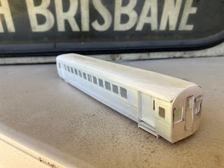
Most of the activity for the week revolved around continuing the build of the QR 2050 class railmotor.  I had some requests from people to show some photos so I have a couple.  I will also talk about how it was built.  I started by finding the corrugated sides.  I had some old AMRI corrugated styrene and it was just 140mm wide, the exact size of between the two side doors.  So this was cut off and slightly bent.  I then cut up some smaller length components for the sections before the front door and after the rear door (for both sides).  I made a floor for the model, and then added some 1mm uprights and cross beams to make a basic frame for inside the model.  To this frame, I added some 2mm styrene strip to the top and middle of the sides and 1mm strip to the bottom of the side to simulate the curvature of the railmotor sides towards the bottom.

The windows!  I hate cutting them out and I glued a HO scale copy of the windows (from the plan) to a section of 0.5mm thick styrene sheet and when the glue dried, I started cutting out the windows.  I had three sections here, the long section between the two doors with 12 windows and the sections in front of the front door and the section behind the rear door.

A frame was then made for the front cab.  The cab shape was cut out by glueing a photo copy of the plan over some styrene, letting it dry and then cutting away.

The various carriage doors were cut to size and their internal windows cut in.  These were the front door, rear door and the side doors.  I still have to make a door for between the passenger compartment and the luggage space.  Maybe tomorrow.

The stairs below the side doors at the rear were added and they look OK.  I think they need a rear backing on them which I have not yet added.  But again a simple task for maybe tomorrow.

The front cow catcher is going to be a tricky job.  I have not yet started to cut this up but I have some ideas.

The front of the Railmotor is on the right.

A more front on shot.

A shot of the other side and from the rear.

Thursday I went to lunch with the boss for my birthday.  The kids were working (or playing) late so we didn’t get to have a birthday cake until about 10:00pm at night.  However, I did get my presents the night before as everyone knew it was an early off to work and university and late night home.  I got a new watch and some Lego.  I put the Lego together on Thursday.  I had not done that for years. 

Friday was drinks at work.  We put away 110 coronas between us all.  A great night.

What was left of the crew.

The night still had some life left in it at this stage.  Only 100 had been drunk.

Saturday was the Redlands Model Railway Exhibition.  I was working on the NMRA stand there with a few others and had many great conversations with the public and members.  I was showing off my railmotor but the main task for the day was to cut out the rear section of the Cassino Station building.  When I say cut out, it means cut out the doors and windows in a section of Slaters Brick sheet with the correct brick pattern for the building.  I also cut out the two ends as well. 

Today I continued on that path.  I cut the windows in the old station master’s office end of the station buildings and then cut out the windows and doors for the main platform side of the station buildings.  I then added the double thickness for the brick pillars that will support the station awning brackets.  On Monday this week, Greg handed over 50 of his 3D printed awning brackets that I will need to paint and I will fit this next weekend.  More progress this afternoon, has meant that the internal walls were installed and the various internal vestibules into the toilets have been installed. 

This shows the back platform side of the station building.

This is the main platform side of the station building.

More work next weekend will be to paint the doors and windows and install them.  I might have to make some templates for the various windows and see if my 3D mate (hint hint) could perhaps print them from an initial scan like he did for the awning brackets. 

So I’m back at work next week for a few days, so that will limit my building activity.  I also need to build up a few more power supplies (for layout lights) as some of my mates want one.  I also need to do some research for Bob on a sound module and look for some very small bogie mount low revolution motors to power my railmotor and a few other railmotors that are in production (or soon will be) around the traps.

Sunday, August 18, 2024

QR 2050 Class Railmotor Build Progress

So this week I did complete the last few light additions to Kyogle platform.  I re-flashed an Arduino and swapped out the one running the lights and the flickering of the ‘bad’ light resumed.  However, the Arduino that I swapped out, was placed on the layout track on the bottom deck at Lismore underneath where I was working on the next deck up at Kyogle and I saw it light up.  Whoops!  It must have conducted some power through the Arduino and now that Arduino is Kaput. 

So I received some plans for the 2000 and 2050 class QR railmotors early this week.  So after perusing these, they were put to good use.  I started scratch building a 2050 stub end railmotor – aka the intermediate car in 3 or 4 car sets.  The railmotor roof I started last weekend did not work out.  So I spent two days looking at the MK II roof.  I laminated a couple of sheets of styrene together and then used my burnishing wheel and shaped it to a reasonable likeness to my railmotor elliptical roof.  So the next step was to work out how to make the curved sheet steel fluted sides of the railmotor.  I found some appropriate styrene in my styrene box and started creating a styrene shell frame and then started putting everything together.  So far I have put everything together and I’m pretty happy with the result so far.  The next railmotor model I do will be better and I might have to work with my 3D designer mate Greg (Hint! Hint!) to see if he can print off all the windows along the railmotor in a single 3D sheet print.  One print for the front windows (in front of the front door), one print for the long middle section windows (between the doors) and a third print for the rear section (after the rear door) windows.  We will then need a set for the left hand side and another set for the right hand side of the railmotor.  Cutting out 12 windows for the middle section of the railmotor is excruciating slow and that is the worst job you can do in scratch building in styrene.  I just hate cutting out windows.  I might have to discuss this with Greg on Monday this week while on our Gympie trip.

On Wednesday this week Greg advised that he had 3D printed some sample Cassino awning brackets.  They look pretty damn good!  The order is in, and I will get them delivered on Monday this coming week.  Next week I think I might spend some time building some supports for a travelling crane for my Rocla Sleeper Siding.  That was why I had the photos up on the blog the week before.  Then I can start looking at building the Cassino Station building.

Yesterday afternoon and today I did more work on my 2050 class railmotor.  I am just putting together the finishing touches, like the skirt at the front and the underfloor detail.  I have no idea what type of motor I will use, but I would like to see if I can use a very small under floor motor.  I would like to see if I can actually make a working model of the throw over seats.  Well at least one – just a proof that it can be done.  Yesterday Kevin, Arthur and myself were chauffeured by PK down to the NMRA meeting at Jack’s place at Palm Beach.  It was a good turn up with about 30 people there.  It was a great meeting, with PK, Arthur and myself all presenting along with Dean.

Sunday, August 11, 2024

Layout Brackets and Styrene Builds

Things did not go as expected this week.  I decided to watch replays of the Olympics during the day instead of doing  work in the shed.  I did take a few photos for a presentation and I did work on the notes that will go with the presentation, but that was about it.  We all went to Tuesday Nighter’s this week at Brendan’s place.  I think there was 8 of us venturing to the end of the earth (or at least you could see the end of the earth from Brendan’s place).  A couple of people were running trains on Brendan’s layout and the comments were that it ran very smoothly in slow speed.  The conversations around the outdoor setting were great and it wasn’t that cold either.  It was a very good night.

On Friday I decided that I needed to get on with building my Cassino Station building.  The first thing I needed to build was a station awning bracket.  These hold off the roof of the station awning.  I built two and went down to the shed and see how they worked on the building mock up.  Well as I had shortened the awning overhand, the awning bracket was two long.  Doh!  Of course I new that.  So I made two more smaller.  I took then back down to the shed and test fitted them and they worked a treat.  So I made two of them.  I quick check of the scale plan and worked out I needed 18 more for the station building and 22 for the refreshment room.  Ah!  I don’t think I want to scratch build that many.

On the left of this photo is one of the awning brackets

Another shot of a bracket

There are actually two needed back to back in this area

You can see down the platform, that these brackets support the roof fascia.

So I made a trip to the Club yesterday for our monthly meeting and I asked Greg if he could 3D print the station awning backets to the measurements of my scratch built ones.  He took one of the scratch built assemblies and he will look into it.  It might take a month for him to finish them among the other things on his plate.  As long I don’t have to build another 40 of them.

While at the Club I was checking out a few other things going on around the Club layouts.  I took some photos and I had an idea for a moving container gantry crane for a future exhibition layout.  I also spoke to some of the QR modellers and I now have some high level plans for a QR Silver Bullet 2000 and 2050 class railmotor.  The dimensions are not that prominent.  I was thinking about what I needed to do to scratch build one of both of these models.  I started some initial tests today, but I think I will have to rethink my intended process.

Some coal wagons and a guards van at the Club.

Grain wagons, ALYs and a low floor wagon.

I nicely coloured and weathered QLX

A model of a travelling crane that I need to scratch build for the layout.

Maybe this week I will get around to completing some lighting additions on Kyogle and Cassino platforms.

Sunday, August 4, 2024

Track Work and Station Progress

Earlier this week I decided to take the XPT for another run.  This time from Cassino platform to as far north as I could go without running into something blocking a crossing loop.  So I went north from Cassino and had an issue inside the helix between Cassino Meatworks and Fairy Hill Loop.  So I went inside the helix and watched what was happening.  I just needed to add some card under the outer rail and the XPT no longer derails inside the helix.  At another point inside the helix, another loop further along inside the helix I did the same fix.  All good now.  The XPT ran well until it went over the bridge over Fawcett’s Creek just north of Kyogle.  I rail joiner had moved between two rails and it was not holding one rail, so there was a height mis match between the two rails.  So I adjusted it and the XPT then ran over that joint very smoothly.  The XPT hit a signal that had fallen across the track just outside the tunnel into Border Loop crossing loop.  So I fixed that and it continued running north.  It got to Acacia Ridge and there was a dead spot in the point work from the single track into the yard fan out.  I changed the points back and forth a couple of times and that came good, and the XPT continued further north.  When inside the Acacia Ridge Yard, I got smart.  It ran via a newish cross over from track no. 1 to the dual gauge track and then run onto the dual gauge mainline and got to the Rocklea Siding standard gauge points and then it had its next issue.  The point actuator wire has too far through the point and every bogie had an issue going through there.  I will make a mental note to use the Dremel to reduce the height of that throw bar and re-run the train.  The train could only get to half-way into the Clapham Yard tracks, as they are all blocked with various trains on the standard gauge.  The train then rack back to Acacia Ridge Yard.  It had issues taking that newly laid turnout in the yard in the opposite direction, so we backed it back up and tried going through the normal track no 1 all the way and everything was smooth as a baby’s bottom.

The standard gauge crossover on dual gauge track where the XPT had issues.

Later in the week, I was able to spend some more time on working on the Cassino Station Building.  I took 5mm off each side of the Cassino Station Platform Building roof.  I then made some decisions about the Cassino Refreshment Rooms.  I adjusted the overhang on the main platform side of the roof, by the same 5 mm as the station building.  But what I actually did was move the back platform side 5mm further towards the platform edge.  Given the required width of the platform overhang on the mainline side, I had to adjust the width of the refreshment room back wall so it had the same overhang as the front of the building.  So that was done, and the measurements all seem to make the platform buildings look good.

The layout of the Refreshment Rooms section of the station building on the Cassino Platform.

The layout of the Cassino Station building at the southern end of the platform.

This view up the platform shows what the platform will look like when complete.  The roof line will need to be constructed separately.

On Wednesday, I finally started to paint up the signal frame that will go inside the Kyogle signal box.  I think it has come up reasonably well. 

The Signal levers that will eventually go into the signal box above.

On Saturday morning I went to Modellers Warehouse to ask if he had some N Scale street lights, as I had purchased some off him previously (years ago).  There is nothing on his website, but he had a look out the back in the warehouse and he have about 6 packets.  I only needed a single packet of 4 lights.  So I purchased them and started planning where they were going to go on the layout on Kyogle Platform. 

I also bit the bullet and gathered up all my old cheap HO street lights that had a grain of wheat bulb and removed them, and then fed an 0402 LED with attached wires, down through the street light post.  I completed 4 and found that I have another 4 lights with grain of wheel bulbs on the layout, that will be swapped over with these LED ones, and then those ones will have their grain of wheat bulb swapped for an LED.

I then realised that I could not find any of the components that I use to create my layout power supplies, (rectified DCC power), so I made out a shopping list for Sunday’s trip to Jaycar.  I went there today and picked them up and purchased enough bridge rectifiers for 10 power supplies and 7 capacitors.  That was all they had of that component.  I have started working out where these will be deployed.  Today I tinned all the electrical components ready for use.